🔀🚀 Isolating Traffic & Ensuring NFS 🖥️ Redundancy with Bonding - Link Aggregation
Published:
👋 Bonding - Link Aggregation cumulus linux / Isolating Traffic / NFS
🎯 Objective
The goal of this project is to 🔒 isolate traffic between 💻 Machine1 & Machine2 while ensuring both can access the 🗂️ NFS server. Additionally, redundancy is implemented for the server’s 🌐 network interfaces to enhance 🔄 fault tolerance.
📌 Constraints
- 🏗️ Layer 2 switches (Cumulus Linux) for Switch 1 & Switch 2.
- Only Switch 3 can use Layer 3 (📡 routing if needed).
- ❌ No additional VMware LAN segments for isolation.
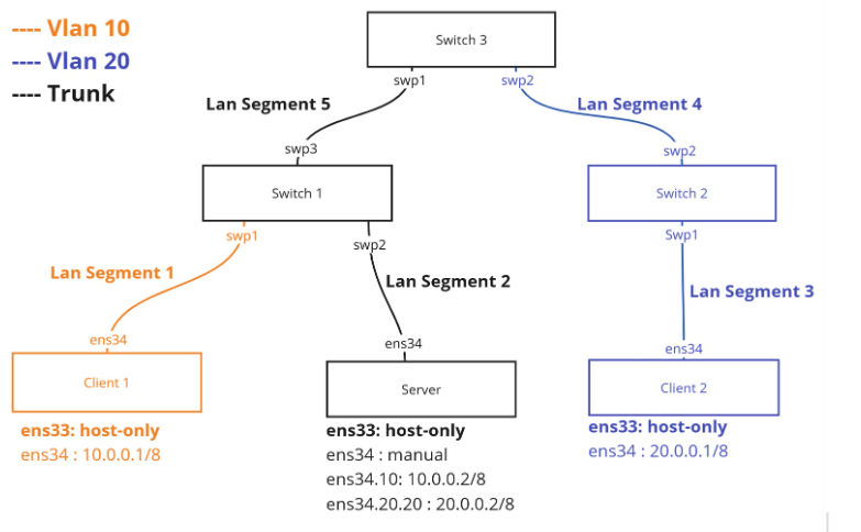
🌐 Network Design Without Redundancy
We divided the 🏗️ implementation into 2️⃣ parts:
- ⚙️ Configuring devices to allow 🖥️ client-to-server communication while isolating clients from each other.
- 🚀 Enabling high availability for the 📁 NFS server.
🔧 Infrastructure Choices
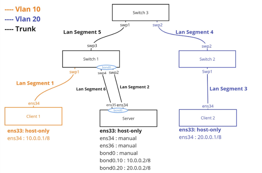
- 💻 Machine 1 & Machine 2: Separated into VLANs (Machine1 in VLAN 🔟, Machine2 in VLAN 2️⃣0️⃣) to prevent direct communication.
- 📁 NFS Server: Interface in 🌈 trunk mode to receive traffic from both VLANs.
- 🖧 Switch 1: 1️⃣ access port for Machine1, 2️⃣ trunk ports (to NFS server & Switch3).
- 🖧 Switch 2: 2️⃣ access ports for Machine2.
- 🖧 Switch 3: Acts as an intermediary switch.
🔌 Switch Port Roles
- Switch1:
- 🟢 swp1: VLAN🔟 (access mode)
- 🌈 swp2: Trunk to 📁 NFS Server
- 🌈 swp3: Trunk to Switch3
- Switch2:
- 🟢 swp1, swp2: VLAN2️⃣0️⃣ (access mode)
- Switch3:
- 🌈 swp1: Trunk to Switch1
- 🟢 swp2: VLAN2️⃣0️⃣ (access mode)
❓ Why VLANs?
We used VLANs to 🏗️ isolate 💻 Machine1 from 💻 Machine2 while keeping 🖧 Switch3 as a Layer 2 switch. Since they remain in the same 🌍 LAN, VLANs allow 🔄 separation without adding 🌐 inter-VLAN routing.
⚙️ Switch Configuration
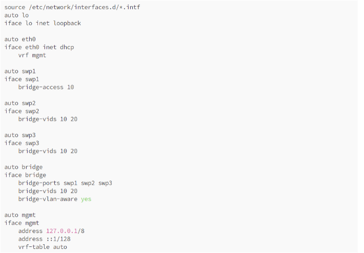
🖧 Switch 1
net add interface swp1 bridge access 10
net add interface swp2,swp3 bridge vids 10,20
net add bridge bridge ports swp1,swp2,swp3
net add bridge bridge vids 10,20
net commit
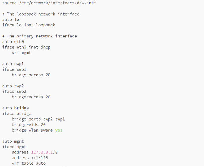
🖧 Switch 2
net add interface swp1,swp2 bridge access 20
net add bridge bridge ports swp1,swp2
net add bridge bridge vids 20
net commit
🖧 Switch 3
net add interface swp1 bridge vids 10,20
net add interface swp2 bridge access 20
net add bridge bridge ports swp1,swp2
net add bridge bridge vids 20
net commit
📁 NFS Server & Client Setup
🖥️ NFS Server Configuration
🌐 Network Setup
Install VLAN support on the server & clients:
apt install vlan
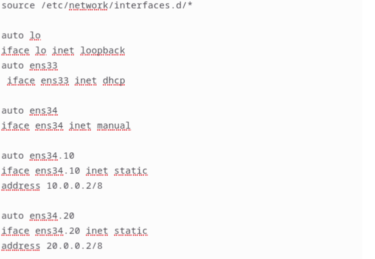
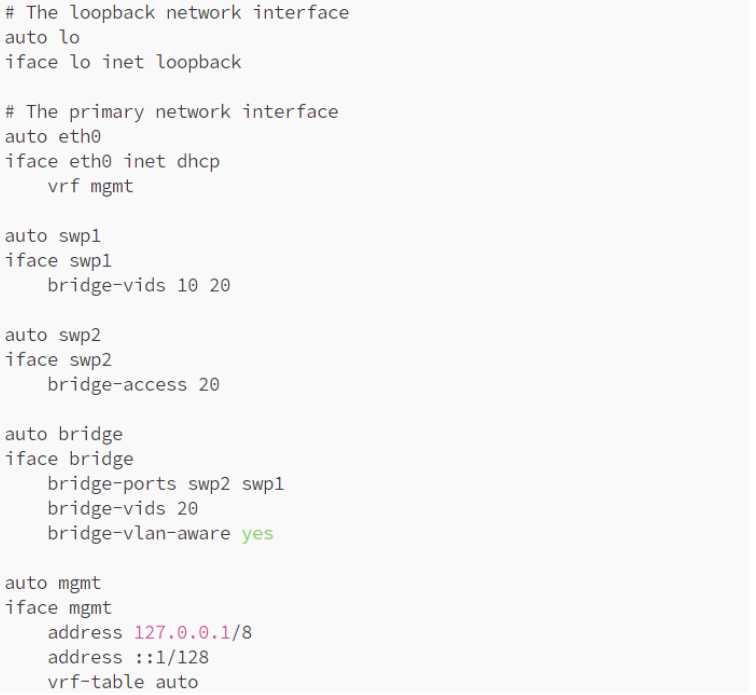
Configure the 📁 NFS server with 🌈 Dual IP (sub-interfaces) to support VLAN-based communication.
📦 NFS Installation
Install required packages & set up 📂 directory sharing:
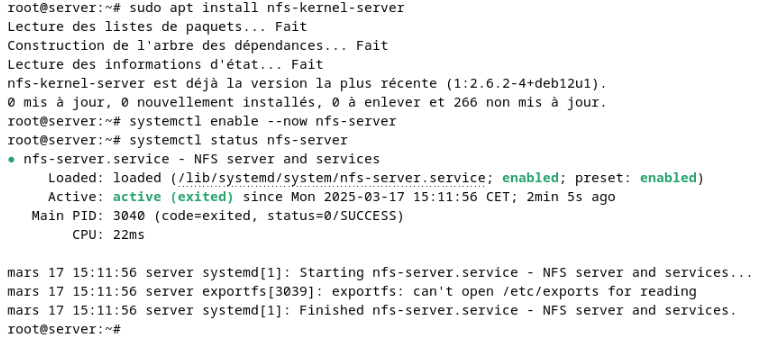
sudo apt install nfs-kernel-server
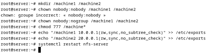
mkdir -p /machine1 /machine2
echo "/machine1 10.0.0.1(rw,sync,no_subtree_check)" >> /etc/exports
echo "/machine2 20.0.0.1(rw,sync,no_subtree_check)" >> /etc/exports
exportfs -a
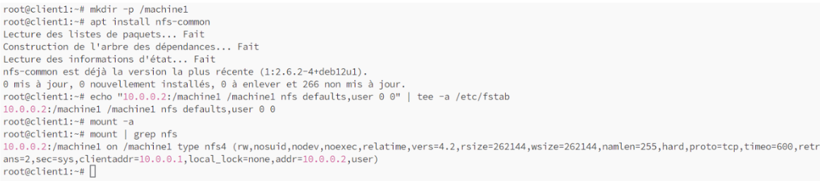
💻 Client Machines Setup
💾 Mounting NFS Shares on Clients
🔹 Machine1:
mkdir -p /mnt/machine1
mount -t nfs 10.0.0.1:/machine1 /mnt/machine1
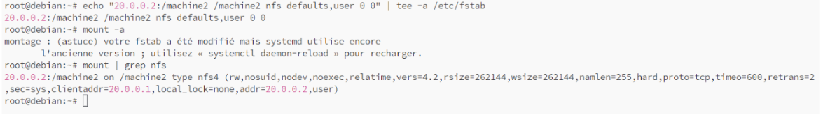
🔹 Machine2:
mkdir -p /mnt/machine2
mount -t nfs 20.0.0.1:/machine2
🛠️ Testing
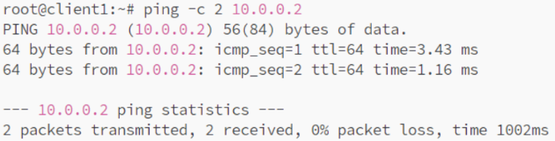
💻 Machine 1 to 📁 NFS Server
📡 Ping Test
ping 10.0.0.1
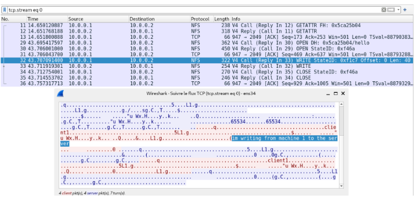
💾 Write Test
🔍 Capture of TCP exchanges:
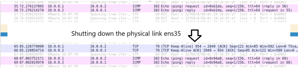
🔄 Adding Fault Tolerance
To improve reliability, we connected the 📁 NFS server to 2️⃣ network interfaces (ens34 & ens35) aggregated under 🔗 bond0 using ⚡ LACP (Link Aggregation Control Protocol). This allows VLANs 🔟 & 2️⃣0️⃣ to pass through while ensuring redundancy.
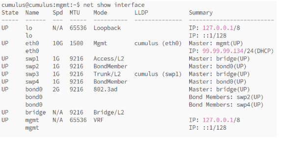
🖧 Switch 1 Configuration for LACP
net del bridge bridge ports swp2
net add interface swp4 bridge vids 10,20
net add bond bond0 bond slaves swp2,swp4
net add bridge bridge ports bond0
net commit
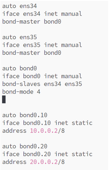
🖥️ Server Configuration for LACP
📈 Performance Testing
Run 📡 iperf tests to measure 📊 bandwidth with & without 🔗 link aggregation:
iperf -c 10.0.0.1 -t 10
iperf -c 10.0.0.1 -P 4 -t 10
🛠️ Testing LACP Failover
With this setup, 🔄 network failures are handled smoothly without disrupting 🖥️ client access to the 📁 NFS server. ✅